At Building Regs 4 Plans, we’ve been preparing for the latest changes to the new Part L, set to apply from June (2022). The Government published the Future Buildings Standards consultation document in January 2021. Contained within this document were the interim Part L, Part F and Overheating Regulations for domestic and non-domestic buildings, and the first steps towards the aim to deliver Zero Carbon Ready homes by 2025.
From June 2022, all new homes will be expected to produce 31% less CO2 emissions than is acceptable in the current Part L.
The new proposals include such upgrades as:
- Waste water heating recovery to ALL showers
- Heating systems flow temperature to be NO more than 55° C
- Photovoltaics – proportional to the ground floor area (e.g. 50m² GFA will require 3kW peak solar panels equal to approx. 18m² [assumed to SE/SW orientation])
- Thermal elements U Values of:
- Walls 0.18
- Windows 1.2
- Floor 0.13
- Roof 0.11
The proposals will also encourage the installation of ground source heat pumps which will allow solar panels to be removed from the design and enable greater flexibility in the specified U-Values of the individual thermal elements.
The new Part L was published in December 2021 with an implementation date of June 2022. Developers must submit their Building Notices, Initial Notices or deposit their Full Plans application by June 2022 or comply with the new regulations set out in Approved Document L 2021.
Accessing Updated Specifications and Detail Drawings
Continuing to register with our site will mean you will always be up-to-date with latest the changes and can easily succeed in achieving building regulations approval. Our unique and easy to use system allows you to draft and submit compliant specifications (from our online library of specs) with the corresponding detail drawings, leading to a finished project in line with the latest Government legislation.
Transitional Arrangements: When to apply the changes
The Amendment Regulations and accompanying Approved Documents L: Volumes 1 and 2 come into force on 15 June 2022. However, the changes will not apply in relation to building work where a building notice or an initial notice has been given to, or full plans deposited with, a local authority before 15 June 2022 provided that the building work is started before 15 June 2023.
For more information, see:
Building Regulations Part L Updates June 2022 Transitional Arrangements
A sample of specifications and details drawings inline with the new Part L, are now available on BuildingRegs4Plans at House Extension Specifications and Detail Drawings: June 2022
Specifications and Details drawings for the June 2022 Part L updates are also available for Premium users for New Builds, Garage Conversions and Loft Conversions.
You can access our specifications by registration at Register for Access
The government has provided its response to the consultation for the proposed changes to Parts L and F of the Building Regulations. A timeframe has now been set out to implement the Future Homes Standard, leading the way to making new homes ‘zero carbon ready’ by 2025.
The Government has proposed that, from 2021, there will be an ‘interim uplift’ in Part L standards. This will compel all new domestic developments to produce 31 per cent lower carbon emissions than is acceptable at present. Further legislation will require 75-80 per cent less carbon emissions within four years.
By 2025, all new homes should be constructed so that ‘no further energy efficiency retrofit work will be necessary to enable them to become zero-carbon as the electricity grid continues to decarbonise’. Fossil fuel heating, such as a natural gas boilers, will also not be permissible in new homes and all new domestic housing will be subject to an overheating mitigation requirement.
Work to existing houses will also be covered by the new regulations and more energy-efficient builds will be expected. For example, thermal elements, such as floors and walls, will expected to achieve a better U-value performance than is currently acceptable and replacement windows, doors and building services will be required to be more energy-efficient.
Transitional arrangements will last for one year and apply to individual homes, rather than an entire developments.
The Code for Sustainable Homes
The Code for Sustainable Homes (the Code) was introduced in England in April 2007 and is the Government’s environmental assessment rating for new homes. It is a voluntary standard designed to improve sustainability by reducing the carbon emissions created by new homes.
The Code enables developers to provide evidence to homebuyers of the sustainability performance of their homes, particularly important as the public are becoming more concerned with the effect their homes are having on climate change and want homes with a reduced environmental impact and lower running costs.
The minimum standards for Code compliance are much more demanding than the minimum standard needed to satisfy Building Regulations and more and more local authorities are requiring self-builders to comply with Level 4 of the Code for Sustainable Homes. However, each individual local authority’s planning policy will decide on the level of Code required.
The Code measures the sustainability of new homes against nine categories:
Energy/CO2 emissions.
Water.
Materials.
Surface water run-off;
Waste;
Pollution;
Health and well-being;
Management;
Ecology.
These categories have been selected for their potential impact on the environment. Some elements are mandatory for compliance; others are optional.
The Code uses a 1 to 6 star rating system depending on the extent to which the build has achieved Code standards, with six stars being the highest level. Credits are given when each performance requirement is achieved, 57 credits are needed for Level 3, 68 for Level 4 and 84 for Level 5. However there are four un-credited mandatory requirements which must be achieved to gain a one star sustainability rating.
These are:
• Environmental impacts of materials
• Management of surface water run-off from developments
• Storage of non recyclable waste and recyclable household waste
• Construction site waste management.
Once the mandatory minimum performance standard has been met for the four un-credited ‘issues’, two further mandatory requirements need to be considered.
Apart from these minimum requirements the Code is completely flexible and other credits can be chosen or traded from other ‘issues’, in order to achieve a higher sustainability rating.
When the build is complete, a post-completion check is undertaken and a certificate will be given to the developer which shows results of the Code assessment and provides a breakdown of how that rating has been achieved. Homes that have not been assessed will have a nil-rated certificate.
CDM REGULATIONS 2015
On 6 April 2015, new CDM Regulations will come into force which will replace the 2007 Regulations. For the first time, the CDM regulations will apply to all projects including domestic jobs. Small and medium size construction projects will now have to provide a written construction phase plan and manage health and safety.
The new regulations will also provide greater clarity, so that all parties involved in a project will have a better understanding of their roles in ensuring a safe construction site.
Principle Designer
The CDM co-ordinator role in the previous CDM Regs 2007 has now been replaced with a new role of principal designer. This means that a member of the design team will be responsible for coordinating the pre-construction phase.
Where more than one contractor is involved on a project, a principal designer and a principal contractor will need to be appointed. While the 2007 regs saw the CDM coordinator role as primarily a pre-construction role, the new regulations will ensure the principal designer and contractor work together during the design phase and throughout the build to completion. This will provide more consistency and continuity, essential to the management of any successful construction project.
Client
The client is considered to have the most influence and responsibility as the head of the supply. The client is responsible for budget setting, providing a skilled team as well as ensuring good standards of health and safety throughout the construction project. The new Regulations recognise this and the client’s duties are now described as ‘must do’.
Competence
The client, principal designer and contractor and any other duty holders must ensure that all persons they appoint have the right skills, knowledge, training and experience to fulfil their functions.
For clarity and ease of assessment this will be divided into the categories of skills, knowledge, training and experience and organisational capability (if applicable).
Health and safety
The client must make sure that a good level of health and safety is in place at the start and maintained throughout the project. The HSE has produced draft legal series guidance (L153) on the legal requirements for CDM 2015. These aim to reduce the number of accidents on construction sites particularly on smaller projects where there is greater cause for concern.
When installing a wood burning stove, a flue liner, building a new chimney or re-using an existing flues, if the installer is not a member of a Competent Persons Scheme such as HETAS a building regulations application will have to be submitted to the Local Authority.
Where it is proposed to bring a flue in an existing chimney back into use the flue and the chimney should be given a visual inspection to ensure the flue is free of obstructions such as dislodged birds nests and it should be checked to make sure that it is of the correct the size and type for the appliance you plan to install. The flue may need to be swept and a smoke test may be required. It is possible that the flue may need to be relined.
Notice plates for hearths and flues
After a stove is installed, it is a building regulations requirement to provide a notice plate permanently posted in the dwelling.
The notice plate gives information on the position of the hearth and/or flue, the flue diameter and essential information about the correct use of the appliance (example shown below).
The notice plate should be displayed either:
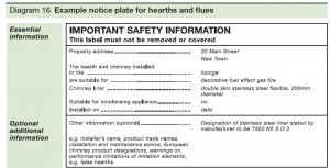
(Reference: Diagram from Approved Document J)
Checklist
Approved Document J provides a checklist in appendix A which should be filled in by the installer. This checklist helps to ensure that the installation of the stove is satisfactory and should be given to the customer and a copy to Building Control.
Carbon Monoxide Alarm
It is a building regulations requirement to fit a carbon monoxide alarm when installing a wood burning stove. These are usually battery powered.
Alarms should be within one to three meters of the appliance and either:
a) on the celling, or
b) on a wall as high as possible (above doors and windows) but at least 150mm from the celling.
Hearth
The stove should sit on a slab of non-combustible material called a hearth, this will protect any combustible materials underneath and around the stove from heat produced from the stove and any falling burning fuel.
The perimeter of the hearth should be clearly defined by either using a raised edge or by raising the level of the hearth in relation to the floor.
The hearth should extend at least 150mm out from the stove at the sides and 300mm in front.
This 300mm distance can be reduced a slightly if the stove is not designed to operate with the door open. A freestanding stove which is not in a recess should have a hearth at least 840 x 840mm.
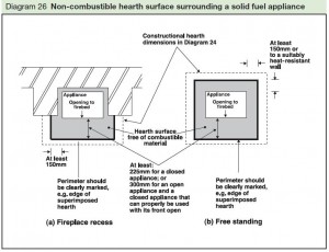
(Reference: Diagram from Approved Document J)
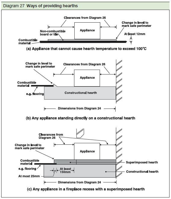
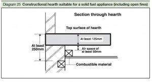
Hearth thickness
If the hearth is on a combustible floor it must be at least 125mm thick and have an air gap of 50mm between its underside and the combustible material (see diagram below).. If an air gap is not possible the hearth should be 250mm thick.
(Reference: Diagram from Approved Document J)
If the hearth is on a solid concrete floor slab or pre-cast concrete beam and block floor then the total thickness of the hearth and floor must be at least 250mm or 125mm thick with a 50mm air gap underneath. Again if it can be proven that the stove will not raise the hearth temperature over 100 degrees centigrade then a 12mm hearth may be used (see diagram below).

(Reference: Diagram from Approved Document J)
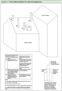
Outlets from flues and chimneys
Flue gases could present a fire or health hazard, therefore the position of the flue termination is essential. The flue outlet should be positioned high enough above the roof and surrounding buildings to prevent it being affected by wind eddies or down drafts (see diagram below).
The flue outlet position is measured to the top of the chimney pot/terminal or 150mm above the top of the masonry stack enclosing the liner – whichever is the lowest.
(Reference: Diagram from Approved Document J)
Flue outlet heights for combustible roofing material
For roofs covered with combustible materials like thatch or shingles greater clearances are necessary (see Approved Document J).
Flue sizes
The flue size must not be smaller than the size of the stove outlet.
If the stove is smokeless fuelled and not exceeding 20kW the diameter of the flue should not be less than 125mm. However whatever fuel the stove burns if the stove is over 20kW but no more than 30kW the flue must not be less than 150mm in diameter. But it is recommended a flue is a minimum 150mm to ensure the stove is safe to use regardless of the type of fuel used.
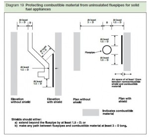
Single skin flue pipes
The stove is connected to the chimney via a single skin enamelled steel pipe, this must be at least three its diameter (OD) from combustible materials. For example a 125mm single skin flue pipe must be at least 3 x 125mm = 375mm from combustible materials. Combustible materials must therefore not be within the grey shaded area shown in the diagram below.
(Reference: Diagram from Approved Document J)
It is possible to separate the flue from the combustible material with a non-combustible shield in which case the distance can be reduced to 1.5 times the diameter of the flue from combustible material.
The shield must extend beyond the flue pipe by at least 1.5 times the external diameter of the flue and an air gap at least 12mm must be provided between the shield and the combustible material.
To ensure the chimney can draw effectively it is important to keep the flue pipe as short as possible.
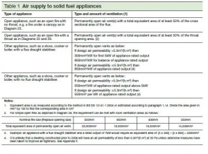
Ventilation for stoves
It is essential that a permanent source of air is provided to allow the smoke to draw up the chimney effectively and allow proper combustion to take place.
Lack of ventilation can cause gases to not fully burn, with the possible result of the production of carbon monoxide, a highly toxic colourless and odourless gas that has potentially fatal consequences.
Ventilation rates are based on the air permeability of the building as well as the rated output of the stove.
Approved Document J provides the minimum standards for permanent supply of air for ventilation. This is particularly important in newer houses where building regulations have ensured buildings are effectively air tight.
In older houses sometimes sufficient air may be already coming through the building which can often be adequate for certain appliances rating and in these cases no additional ventilation is necessary. Ventilation is also not required if the stove draws its air supply directly into the appliance through a duct.
Below is a table from Approved Document J stipulating ventilation requirements for stoves.
(Reference: Diagram from Approved Document J)
The vent should be placed so that the occupier is not bothered by draughts or noise and therefore likely to block the vent.
The vent can be fixed in the walls, ceiling or floor and does not have to be in the same room as the stove. Ventilation can also be provided from another room which itself has permanent ventilation. It is preferable to position it close to the stove to reduce draughts and retain room heat, but should not be placed in the fire place recess, except on the advice of a specialist, as dust or ash might be disturbed by the draughts.
Some vents are available that can be installed using a 125mm core drill. They incorporate a series of baffles inside the duct to reduce wind noise.
Twin wall flue pipe.
A twin walled flue pipe should be designed to suit the appliance and kept a suitable distance away from combustible materials (see diagram below).
There should also be a guard provided where the flue pipe passes through a cupboard, storage space or roof space.

(Reference: Diagram from Approved Document J)
Lining existing chimneys
Flexible Steel liners are made from double skinned, high quality stainless steel. They cannot be used in a new chimney, but are suitable for relining an existing chimney. This type of liner can accommodate bends in the chimney. It is fitted by being lowered down or pulled up the chimney. The liner should be installed in one continuous length with no joints. Coring balls should not be used on a metal flue system.
Factory made relining systems are often clay, ceramics or refactory concrete. The liner is lowered down the chimney on guide ropes with locating bands at the joints.
New Masonry chimney
The most common type of masonry chimneys are brick, block, stone or prefabricated chimney block systems with either clay/ceramic liners or refactory concrete liners.
Masonry chimneys should have liners suitable for the stove that is being fitted. Pumice, clay, or concrete liners can be used. Joints should be kept to a minimum and bends and offsets should be formed only with matching factory made components. Liners need to be placed with the sockets or rebate ends uppermost to contain moisture and other condensates in the flue. Joints should be sealed with fire cement, refractory mortar or as stipulated in the manufacturer’s instructions.
Spaces between the lining and the surrounding masonry should not be filled with ordinary mortar, but with a weak insulating concrete backfill – i.e. leca, vermiculite, or perlite.
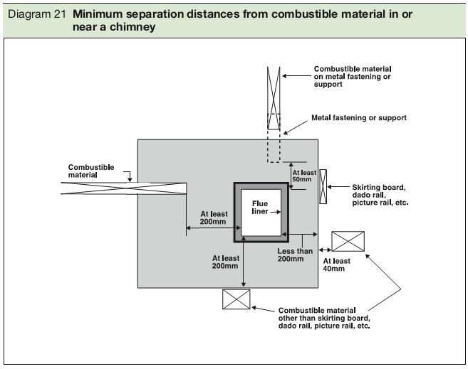
All new chimneys must be built on suitable foundations with a damp proof course 150mm above ground level and appropriate weathering where they pass through the roof.
It is essential to have adequate clearance from any combustible material. Joists, floorboard or rafters must be spaced at least 40mm from the chimney outer face or 200mm from the inner surface of the flue.
Factory-made metal chimneys
These systems are used as an alternative to masonry chimneys and consist of interlocking sections with a stainless outer casing.
Access inspection hatches of at least 300mm2 must be provided to enable commissioning and maintenance checks.
If the metal chimney passes through a cupboard, room or roof space it must be guarded to prevent any combustible material being closer than the minimum separation distance mentioned above. Where passing through a floor, manufacturer’s fire stop components must be used to separate the chimney from any timber to maintain the fire resistance.
Part P Electrical Safety
In 2005, the Government introduced Approved Document P Electrical Safety into the building regulations (England and Wales). This regulation ensures all domestic electrical installations and alterations made to existing installations (except some types of minor work) are designed and installed to meet the standards set out in the building regulations. Therefore, by law, all homeowners and landlords must be able to prove that all electrical installation work meets the requirements set out in Part P, or they will be committing a criminal offence. Local authorities can instruct you to remove or alter electrical work that does not meet these requirements.
Part P stipulates that when some someone is planning to undertake electrical works they must either:
- Tell the local building control about the installation in advance so that the council’s building control officer can inspect the work, or
- Employ an electrician who is registered with one of the five government-approved competent self-certification schemes. The ‘competent person’ must provide a self-certification certificate to the customer and forward a copy to the Local Authority within 30 days.
Competent self-certification schemes.
There are two type of scheme. The first being Full Scope registrations. With this scheme an electrician can register with one of the following bodies; BRE Certification Ltd, British Standards Institution (BSI), ELECSA Ltd, NAPIT Certification Ltd, and NICEIC Certification Services Ltd. The second scheme is called the Defined Scope registration. The bodies which cover this scheme are CORGI, ELECSA, NAPIT, NIC or FTEC. This scheme enables associated trades to carry out a limited amount of electrical work in dwellings as part of their associated work activity. For example: installing new circuits from the consumer unit or adding additional points to existing circuits.
Changes to Part P
In April 2013, the Government made important changes to Part P of the Building Regulations. The two main changes were:
1. The extent of the work that must be checked by a building control body unless undertaken self-certified by an installer registered with a competent person scheme has been reduced.
2. There is now provision to allow the use of a registered third party to certify notifiable work.
From April 2013, electrical work in kitchens or external electrical work will no longer be notifiable apart from installing a new circuit.
Electrical installation work that is now notifiable includes:
A The installation of a new circuit
B) The replacement of a consumer unit or
C) Any addition or alteration to existing circuits in a special location
A special location means:
A) A room containing a bath or shower, the space surrounding a bath tap or shower head where the space extends
- vertically from the finished floor level to a height of 2.25M or the position of the shower head where it is attached to a wall or ceiling at a height higher than 2.25 metres from that level and
- horizontally where there is a bath tub or shower tray, from the edge of the bath tub or shower tray to a distance of 0.6 metres. Or where there is no bath tub or shower tray from the centre point of the shower head where it is attached to the wall or ceiling to a distance of 1.2 metres.
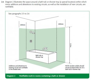
(Reference: Diagram from Part P Approved Document, 2013)
The requirements of Part P also apply to a room containing a swimming pool or sauna heater.
Non- notifiable work
All other electrical installation work is not notifiable – namely additions and alterations to existing installations outside special locations, and replacements, repairs and maintenance anywhere.
Installing fixed electrical equipment is within the scope of Part P, even if the final connection is by a standard 13A plug and socket, but is notifiable if it involves the installation of a new circuit, the replacement of a consumer unit or work in a special location as described above.
Certification by a registered third party
The second major change relates to the use of a registered third party to certify notifiable work.
Before April 2013, electrical works covered by Part P undertaken by a person not registered with a competent persons’ scheme could only be deemed compliant by local authority building control.
Under the new Part P, the third party certification schemes allows electrical works undertaken by those who are not registered with a competent persons scheme to get the work inspected and tested by a registered third party to confirm that it complies with the building regulations.
Within 5 days of completing the work, the installer must notify the registered third-party certifier who, subject to the results of the inspection and testing being satisfactory, should then, within 30 days, complete an electrical installation condition report and give a copy of the building regulations compliance certificate to the occupier and give the certificate or a copy of the information on the certificate, to the building control body.
It could be considered that the new Part P is really a dumbing-down of standards resulting in incompetent electrician and diyers producing substandard or potentially dangerous work, putting lives at risk.
Unvented hot water systems are now being chosen over more traditional water heating solutions for new build and refurbishment projects.
The advantages of this system are:
- The system is fed directly from the mains cold water supply; therefore no additional tanks are required. This reduces pipework and allows the roof space to be used for additional storage or living accommodation.
- The unit can be installed in any suitable location as the system does not rely on gravity for the adequate flow of water.
- A high pressure flow of water is delivered even if more than one tap or shower is being used.
- The system can be connected to solar water heating systems and/or solar panels.
- Noise is reduced as there is no refilling of a storage cistern.
- The risk of freezing and burst pipes in roof spaces is eliminated.
- An immersion heater can be used to supplement the heating of the water reducing the dependence on the boiler.
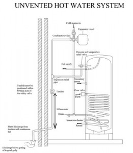
Because the unvented cylinder operates under high water pressures, built in safety measures are required these include:
- A combination valve – This is positioned on the incoming cold water pipe and incorporates 3 features; a pressure reducing valve, which keeps the pressure at a constant level; a line strainer, which filters incoming cold water ensuring it is clean and free from any grit that may damage the system and a single check valve, which prevents contamination of the water supply from backflow.
- An expansion vessel – This stores the water produced when the water in the cylinder is heated and expands. The expansion space can also be provided within the cylinder, this is known as an ‘air gap’ or ‘bubble top’ system. The internal air bubble is created when the system is commissioned.
- Thermostats – The thermostats are in place to prevent the temperature of the water in the system exceeding 99°C. These include a control thermostat which is set to maintain the temperature of the water between 60-65°C; this gives the first level of protection against the overheating of the water. A second thermostat incorporates a thermal cut-out which switches off the immersion heater and shuts off water from the boiler if the control thermostat fails and temperatures reach between 85-89°C. This thermostat has manual reset feature in place which cannot be self-resetting.
- A temperature and pressure relief valve is fitted near the top of the cylinder. This is set to 90°C + and is designed to remove pressure from the system preventing the water temperature exceeding 99°C. It provides protection against the failure of the pressure reducing valve, failure of the expansion vessel or the loss of the internal air bubble.
The temperature and pressure relief valve releases water under fault conditions via a discharge pipe to a tundish where the water released becomes visible. The tundish must be positioned within 500mm of the valve in a safe and visible position so that the householder will be alerted to a fault condition.
Discharge pipes are typically 15mm up to the tundish, and then 22mm from the tundish to a safe discharge point outside the building. The pipe from the tundish should never be less than the size of the tundish outlet. It should be vertical, at least 300mm long before any elbows or bends and be installed with a continuous fall of at least 1 in 200 thereafter.
The discharge pipe should be made of metal or other suitable material which can be shown to withstand the high temperatures.
The Local Authority Building Control must be notified of the installation of an unvented hot water storage system as they are subject to the legal requirements of Building Regulation G3. The system must be installed by a ‘competent person’ who holds the relevant qualification for the installation of unvented hot water cylinders. The installer must be able to provide a card issued by a body such as the Institute of Plumbing (IoP) or the Construction Industry Training Board (CITB).
If the installer is registered with a competent person scheme for this work, building control do not need to be notified in advance. Instead installers will self-certify their work and give the owner a certificate issued by the competent persons scheme operator.
Air holds a certain amount of moisture as invisible vapour. Condensation is caused when the moisture in the air comes into contact with a cold surface and condenses at the dew point (the temperature at which the air becomes saturated). The increasing levels of insulation, impermeable cladding materials and other new methods of construction has led the potential for condensation to rise.
There are two types of condensation: surface condensation and interstitial condensation.
Interstitial condensation is when the the dewpoint is within the structure. This will often be on the warm side of relatively vapour resistance layers.
Surface condensation is when the the dewpoint occurs on a surface and is often noticed when mould or moisture appears on the surface of a wall or window. In many cases, the problem can be solved by simply washing off the moisture or mould or providing adequate mechanical and/or natural ventilation. However, condensation can cause more serious problems, for example:
- the build up of mould spores may lead to significant health problems.
- condensation on a window pane may drip down and rot the frame.
- condensation collecting on roof rafters may lead to degradation of the timber structure.
Architects should consider this condensation risk at the design stage and minimise potential problems by specifying suitable ventilation as well as ensuring surface temperatures are kept high by providing adequate insulation and heating. The ideal ventilation system would extract internal moisture laden air from activities such as cooking, drying clothes and hot showers, to the outside, and replace it with external air.
This could also utilise a heat recovery system for optimum temperature control and energy saving. Approved Document F gives the minimum standards required for the background, purge and extract ventilation of buildings.
Interstitial condensation can be controlled by considering the vapour resistance of the materials used in construction, by ventilating air spaces in suspended floors, cold roofs and cladded timber-framed walls and by the use of vapour control layers.
Vapour control layers provide a physical barrier against moisture in the air reaching the internal structure. They can be in the form of a polythene membrane, foil backed plasterboard, taped insulation or a suitable coating applied to the internal surface of an element. Vapour control layers should be positioned on the warm side of the insulation. Any pipes, electrical fittings, etc. which pass through the vapour control layer should be kept to a minimum and taped and/or sealed.
Thermal bridging can cause condensation to collect on cold spots on areas such as wall-floor junctions, roof eaves and areas around window and door openings. With careful design of the insulation at these vulnerable points, condensation risk can be reduced.
As condensation can substantially reduce the thermal performance of insulation and a building’s structural integrity, a Condensation Risk Analysis can be undertaken at the design stage to assess the likelihood of condensation problems. Many of the insulation manufacturers offer this service.
A Condensation Risk Analysis can predict the risk of interstitial or surface condensation by analysing the components of the building’s elements, the order in which they assembled, the use of the building and its geographical location.
Architects often query the use of trickle vents conflicting with the air tightness required in new buildings. Professionals argue that by providing homes with such little air leakage the condensation problem is exasperated. Although trickle vents must be provided and must be controllable, to work affectively they may need to be open for the majority of the day, making a mockery of the need for an air tightness 10 m³/(h.m²) at 50 Pa required by the building regulations.
To encourage the conversion of heating systems to renewable heat technologies, the government launched the domestic Renewable Heat Incentive (RHI) in April 2014.
This is an incentive administered by the energy regulator Ofgem E-Serve which provides financial assistance, helping people to make their homes more energy efficient . The RHI goes some way towards reaching the government’s target of producing 12% of the UK’s heating from renewable sources by 2020.
Renewable heat sources use naturally replenished energy rather than fossil fuels to generate heat.
Renewable heat technologies applicable to the scheme are air source and ground source heat pumps, biomass boilers and solar thermal technologies. Properties reliant on the live gas grid are likely to save the most on fuel bills.
Renewable heating technologies are much more effective in well insulated buildings.
Therefore, to qualify for the incentive, the property must first have a Green Deal Assessment carried out and any insulation recommended by the assessor will need to be installed.
The scheme is mainly used for single homes and can be taken up by homeowners, social and private landlords but is not available to new build properties other than self-build projects.
Payments for the hot water and heat generated are index-linked for inflation and made to the applicant quarterly for seven years. The amount received depends on the type of system installed and the size of the property.
However it can be up to 8.5p/kWh. A payment calculator developed by the Department of Energy and Climate Change (DECC), the Scottish Government and the Energy Saving Trust can be used to work out how much is likely to be paid.
In the first seven weeks of the Domestic Renewable Heat Incentive opening, 1,000 installations were accredited onto the scheme. Although advertising to the general public appears to be lacking.
Most people in the best position to take up the incentive don’t seem to be aware of its existence. It is only when other work is already being carried out on a property that the architect may mention this scheme.
Is it a missed opportunity to really improve the energy efficiency of the existing housing stock?
Or could it be that limited funds mean that the government can only make a token effort?
On 6 April 2013 the way in which Building Control worked with builders and home owners changed.
Instead of carrying out site inspections at fixed stages, the Local Authority were given the option of providing the builder/applicant with an Inspection Service Plan before commencement of works.
This plan will identify the stages of work where Building Control perform their inspections. The number and type of inspections will depend on the scope and complexity of the works, the construction methods used and the ground conditions, as well as the builder’s experience and competence.
This, in turn, is likely to be reflected in the fee that Building Control charges.
(‘…likely to…’, because these changes are yet to be implemented by some authorities.)
These inspections are expected to include the following stages:
-
When you start work
-
Foundation excavations – to assess ground conditions, required depths, the thickness of your concrete.
-
Damp proof course/Damp proof membrane – this includes any brickwork below ground level, floor insulation and preparation for your ground floor.
-
Drains – before drains are covered over.
-
External wall – to ensure proper construction and placing of insulation.
-
Completed roof structure, before removal of scaffolding and placing of insulation.
-
Before plastering
-
At completion.
Previously, for domestic work, Building Control would need to have been notified two days before commencement of the work and not more than five days after work had been completed, but now you must also notify building control at each stage outlined in your Inspection Service Plan in order for them to carry out site visits at those particular stages.
It is important to be aware that if the builder or owner fails to notify Building Control of the stages set out in the plan, they may not be issued a completion certificate.
The idea behind the changes is that service plans will provide flexibility to the site inspection process and allow Building Control to risk-assess builders in order to ascertain whether fewer visit could be carried out on particular jobs.
In theory this should lead to reduction in fees on jobs where Building Control play a smaller role and could potentially entice developers back from Approved Inspectors.
On the other hand more visits may be required for more complex jobs or where the builder is deemed less experienced (or even less trustworthy). Building Control are now able to charge more for these projects, hopefully leading to increased compliance of the building regulations overall.